When using SOLIDWORKS Simulation probes in a study, we typically want to take readings from the same location over and over regardless of the mesh or changes to the model. This is easy if a vertex already exists in the location we want to probe, but if no vertex exists in that location, our probe will be imprecise at best and can move around with changes to the mesh or model.
The reason for this is that when a user tries to probe a specific point on an unbroken face in the model, the software will consider the location and will find the closest mesh node to that location and provide data for that node. It’s highly unlikely that any node in the mesh will fall precisely at that location randomly. If there are changes to the model, or if the model is re-meshed with different settings, the location of the node in the mesh will change and as a result, when the same point is probed the next time, it will again consider the location and will find the new mesh node closest to the probe. The end result is that the probes provide data from two slightly different points in the model.
The SOLIDWORKS Simulation Probe Problem
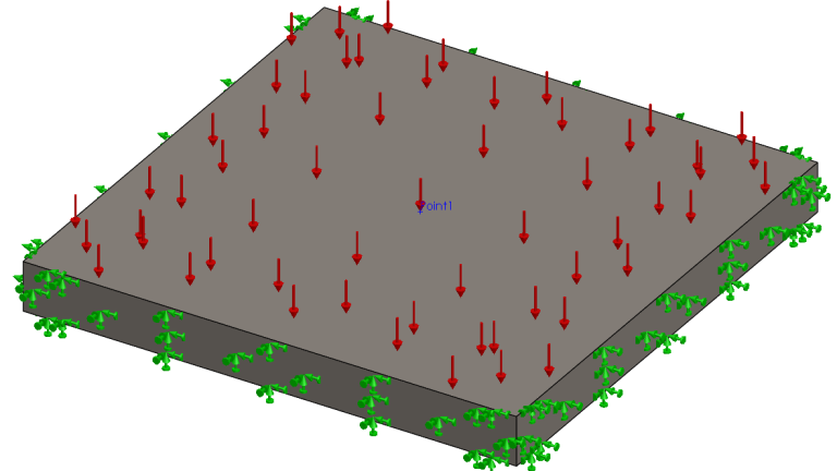
Take the simple plate as an example. Assume all the edges are fixed and there is a pressure acting downward on the top face. Let’s say we want to probe for deflection at the exact center (Point1) of the plate, which is conveniently located at (0, 0, 0) in the default coordinate system for this model.
 A simple SOLIDWORKS Simulation study setup
No vertex exists at this location, so if we try to probe it, we will get the mesh node closest to that point. The image below shows the meshed model and the resulting imprecise probe point. The mesh in this example is overly coarse to demonstrate the issue.

Simulation probe missing desired location
Notice that the probe is not aligned with Point 1 as intended. It’s going to provide data from the closest node to that point, which is offset from the actual location we want. To compound the issue, if we modify the geometry and re-mesh the part, the next probe will find a different node in a different location. This will result in erratic data that could drastically change between studies.
Solving the Problem in SOLIDWORKS Simulation
The solution to this problem is simple. We need to add a vertex to the model in the location that we want to probe. There will always be a node in the mesh at the location of a vertex, so if we place a vertex at the location we want to probe, we can ensure we always pull nodal data from the same precise location every time.
One simple way to do this is to add a Split Line feature to the model. If we take the example part and add a Split Line feature, we can ensure that a vertex exists in the model in the location we want to probe. The image below shows the model after splitting that generated a vertex at the center of the plate. Notice that the geometry or dimensions of the model never changed and we only effected the topology of the faces.

Simulation model with split faces
After splitting the face of the model and remeshing, you can see that the mesh perfectly passes the vertex. By doing this, you can create a consistent location to place your SOLIDWORKS Simulation probes regardless of mesh changes.

Mesh aligned perfectly with the created vertex
Other Considerations
If you are using simulation probes on sheet metal parts, it is important to split both the top and bottom faces at the same place. Doing so ensures the automatic mid-surface generation is able to recognize the geometry correctly and align the mesh. Additionally, adding Workflow Sensitive Sensors to the vertex will allow for consistent information across studies and parameters.
Looking to decrease costs and increase design iteration efficiency? Contact one of our SOLIDWORKS Simulation experts here.
Cloud Software
Berita Olahraga
Lowongan Kerja
Berita Terkini
Berita Terbaru
Berita Teknologi
Seputar Teknologi
Berita Politik
Resep Masakan
Pendidikan