Very rarely does a design hit the mark on the first attempt. Making changes is a fundamental step of creating, evolving, and improving your designs and products. SOLIDWORKS xDesign makes the iterative process of making changes extremely quick by providing streamlined tools and time-saving menus.
Let’s review the cam component in an assembly for the internal components of a jigsaw tool. To design this component, we heavily relied on other geometries to define its shape and size. It would be incredibly powerful for design changes to propagate down to the other parts in the assembly
Understanding Design Changes to the Shaft
Currently, the red gear drive shaft in the image below has an outer diameter of 8 millimeters. That diameter dimension is not connected to other dimensions in the design and only exists in the context of that single component.
 Internal components in the jigsaw assembly
To better focus on a specific part, we can isolate the shaft to review its dimensioning. Isolating a component will hide everything else in the assembly, so we can drill down to a single component (or group of components). The diameter is driven (shown by gray coloring), and its edge is not connected to the desired edge for an in-context relationship. In the gear drive shaft component, we can see external references, and we can isolate those references.
Making Changes to Other Dimensions
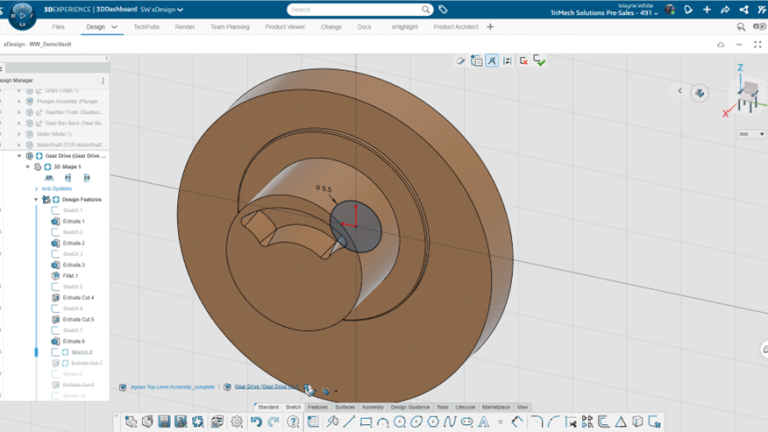
Reviewing another component that the shaft is associated with, we see that the internal diameter is set to 8 millimeters. Below, I changed the diameter to 9.5 millimeters to update the component. On the bottom left of the xDesign graphics area, breadcrumbs allow an easy way for the user to return to the top-level assembly. Breadcrumbs allow the user to focus on the modeling intent and possibly minimize other portions of the interface, such as the feature tree.

Adjusting the diameter of a part in SOLIDWORKS xDesign
Adding In-Context Relations
Going back to the drive shaft, we can see that it is not updated to the current 9.5 millimeter dimension. To link the driver shaft to the other components, first, the existing dimension needs to be removed. From here, an equal relation can be added between the gear shaft and the gear draft. SOLIDWORKS xDesign provides contextual options based on our selection to streamline the process of adding relations.

Isolating a relationship to break current connections
Reviewing the two components that were changed, we can now see the models are linked together by the relation, and any dimension changes to one will reflect in the other. Making design changes in SOLIDWORKS xDesign is a familiar experience to users of SOLIDWORKS or other CAD ecosystems. External references allow users to establish connections to other geometries.

Adding the in-context relation
References can be broken and established in expected fashions to define the design intent necessary for the project. In this case, we’ve introduced redundancy to the model. Our design intent would be to have the diameters related to one another, and through the power of SOLIDWORKS xDesign, we can easily create these dependencies.
To learn more about SOLIDWORKS xDesign, read our other articles here.
Cloud Software
Berita Olahraga
Lowongan Kerja
Berita Terkini
Berita Terbaru
Berita Teknologi
Seputar Teknologi
Berita Politik
Resep Masakan
Pendidikan