Recently, The TriMech Group has partnered with the Disc Golf Pro Tour to help support the growth of one of the most electric sports alongside its passionate community of athletes and fans. What better way to promote the collaboration between TriMech and Disc Golf Pro Tour (DGPT) than by showing how to use a skeleton sketch for top-down assembly modeling to model a disc golf basket?
There are many ways to model and assemble parts in SOLIDWORKS. The bottom-up approach is where individual parts are designed separately and then brought together in an assembly. This method is the most commonly used modeling method for production. There is also the top-down modeling approach, which can be useful when parts are tightly related and share design intent. This is a great way to ensure everything fits together from the start.
How to Model a Disc Golf Basket
Before I modeled the disc golf basket, I needed to figure out the sizes and specifications. The Disc Golf Pro Tour is the official Pro Tour of the Professional Disc Golf Association (PDGA) – the sport’s governing body. The PDGA website has the standard dimensions for Championship, Standard, and Basic disc golf targets. I’ve decided to design the championship disc golf basket since that is what will be used on the Disc Golf Pro Tour.
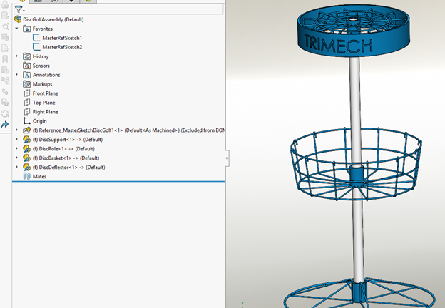
The overall design that I’ll be creating today looks like this and uses a top-down modeling approach. For my design I didn’t include holes in the parts for set screws and some of the additional things to make it fully functional,
 Disc golf basket created in SOLIDWORKS
Creating a Top-Down Assembly Skeleton Sketch
To begin the process, I created a skeleton sketch (also known as a master sketch) that serves as the foundation for my entire disc golf assembly. This sketch has all the main dimensions of the different parts (basket, deflector, pole, support) and all the dimensions for these features. This sketch is then saved as a single SOLIDWORKS part file that will be referenced in each component later when working in the assembly. This will ensure that all parts follow the original design intent and will allow global changes of the sketch to update both the parts and the assembly.
Below is the overall sketch plus an image of the deflector portion of the sketch. While it may appear cluttered, we can easily pinpoint the dimensions we need later when working with the overall assembly.

Disc golf basket skeleton sketch
Creating the Disc Golf Deflector
I then created a new part and used the Insert/Part command to insert the skeleton sketch part. From there, I revolved the main components using the centerline and contours from our sketch. I then created a sweep of the support using a center profile and the single open-loop line I created in the master sketch.

Using the Sweep command
By using circular patterns, I was able to quickly duplicate my geometry around the rest of the deflector. From there, the inner loops that the chain will attach to later were created in a similar fashion. Thanks to the skeleton sketch, there has been very little, if any, dimensioning needed for the individual assembly components.
After adding the material, I sketched the word “TRIMECH” on the front plane, used the Wrap command to etch it into the outer diameter, and then added color to the appearance. At this point we have a regulation-accurate and very well-branded disc deflector.

The completed disc deflector
Note that this part was created using a multi-body technique, so the standard bill of materials will not show the breakdown of the individual parts. A simple way to get a parts list is to convert this into a weldment part, which will automatically create a cut list for the separate bodies. On the drawing, the Weldment Cut List table can be added, which will have the quantities of the different parts/bodies.
Creating the Disc Golf Assembly
To create the disc golf assembly, I started by inserting the skeleton sketch part so that I could make major updates to all the assembly components by modifying the single sketch. By right-clicking on the Master Sketch part, I’ve set it as an Envelope part so that it doesn’t show up in the bill of materials for the assembly. I then right-clicked on the sketches inside the Master Sketch part and added them to the favorites of the assembly so that I could easily edit the entire assembly from that master sketch without having to hunt it down in the tree.

Skeleton sketch added to the assembly favorites
When inserting the rest of the parts, I can simply click the “Fix” toggle under the “Fix/float component on insert” option. This will automatically fix each part to the origin, which will be identical for all parts since they are all based on the master sketch part and origin.

Setting the new component to “Fixed”
Updating the Disc Golf Assembly
With this top-down assembly modeling approach using the skeleton sketch, I can now edit the parts and assembly all within the assembly, using the Master Sketch that I’ve added to the favorites. After making any updates, the part sizes and the assembly positions will all update automatically.

Editing the top-down assembly
The Differences Between Top-Down and Bottom-Up Assembly Modeling
There are several advantages to working with a top-down assembly approach using a skeleton sketch. However, there are also a lot of different considerations to think about when choosing your method. Let’s explore some benefits and differences between bottom-up and top-down assembly practices.
Bottom-Up Assembly Modeling
- The traditional approach used in design and manufacturing.
- It starts with individual components and parts that are modeled separately.
- Individual components are added to sub-assemblies and the main assembly.
- This design promotes the reuse of parts since parts are easily brought into other assemblies
- It’s easy to learn and much more flexible across the design spectrum.
Top-Down Assembly Modeling
- Typically used for preliminary or prototype work.
- Begins with the overall assembly or layout being created.
- Parts are created in the context of the assembly being either using a skeleton sketch, a master model, or in-context features.
- Top-down assembly modeling can help control relationships and fit between parts.
Additional Top-Down Design Considerations
While top-down assembly modeling might be a clear choice for your team, there are a few other considerations to keep in mind:
- Design Intent – Do you have a clear understanding of the big picture?
- File and Reference Management – There can be more complexity with handling references and ending up with broken links or circular references.
- Uniqueness of Parts – They will always be referenced to the master sketch or assembly and not easily used elsewhere.
- Large Assembly Performance – With larger assemblies, there may be reduced performance as it can be resource-intensive with in-context features.
- Design Complexity – Managing top-down designs can become challenging for someone who didn’t do the original design to understand the intent.
SOLIDWORKS top-down assembly modeling made creating a disc golf basket assembly a breeze. Stay tuned to our blog in the coming weeks for more SOLIDWORKS and disc golf content.
To learn more about top-down design techniques, register for an upcoming training class here.
Cloud Software
Berita Olahraga
Lowongan Kerja
Berita Terkini
Berita Terbaru
Berita Teknologi
Seputar Teknologi
Berita Politik
Resep Masakan
Pendidikan