SOLIDWORKS lets us leverage 2D images as an overlay in the modeling environment to assist with design development.
This is extremely helpful when we try to reverse engineer a product, begin the product development cycle, or collaborate more easily on designs. The Sketch Picture command allows us to import different file types and start modeling from a reference.
How to Access the Sketch Picture Command
The steps to access the Sketch Picture command are as follows:
- In the SOLIDWORKS title bar, open the Tools menu.
- Expand the Sketch Tools section.
- Open the Sketch Picture command.
There are a variety of image file types available to use in SOLIDWORKS, including JPEG, PNG, and TIFF. The most important thing to keep in mind is maintaining a high-resolution, high-contrast image with crisp edges to make the future workflow easier. It is recommended to preprocess the images in another software to help with the resolution and contrast, if necessary.
 Available file types for Sketch Picture
Placing and Scaling the Image
After opening the image, it will be inserted coplanar into the current sketch, usually with the lower left corner at the origin. The Sketch Picture Property Manager helps us understand the size, location, and aspect of the graphic image. A common issue we encounter with graphic files is that we have little control over the size at which it is inserted into SOLIDWORKS.
The size of the graphic picture added to the sketch is based on the creation device, unit system, and DPI resolution of the graphic. They usually come at a very large scale and need to be resized. The automatic Scale Tool will help by aligning it in the Sketch Picture with a real-world feature of known size.

Scaling a Sketch Picture based on a known dimension
To scale the image used as a Sketch Picture, use the following steps:
- Drag the non-arrowhead end of the Scale Tool and drop it on the graphic at a logical base point.
- Drag the arrowhead end to the other extreme of the referenced edge or feature.
- Release the mouse button. In the Modify Dialog that appears, key in the real-world length of the feature.
- Click OK, and the software will scale the graphic picture by the ratio of the length of the Scale tool to the real-world length you keyed in.
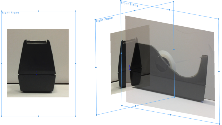
For example, a Sketch Picture was originally inserted at 57″ x 41″ and we properly scaled it down by specifying 6″ for the real-world overall length. Now you can move and rotate the image so the sketch origin is coincident with a logical anchor location in the picture. Repeat this process as needed to insert additional Sketch Pictures on adjacent respective planes.

Orthogonal images ready to create a part
Creating a Model from Images
The Sketch Pictures can now guide sketch creation, and we can manually trace the perimeter or the boundaries of the referenced image with common sketch elements. Alternatively, if you turn on the Autotrace Add-in, SOLIDWORKS will look for the borders or margin between the light and dark areas and automatically create the sketch geometry. This is where a high-contrast image is extremely helpful.

SOLIDWORKS sketches and model created from reference images
Creating features from the sketches is straightforward now, and the Sketch Picture command helps validate our design choices. With the easy, reproducible steps, you’ll be reverse engineering and creating unique geometry in no time. With your SOLIDWORKS Subscription through TriMech and Javelin, you have access to our deep technical knowledge to help tackle design challenges with tools like these.
To learn more about your SOLIDWORKS Subscription benefits, click here.
Cloud Software
Berita Olahraga
Lowongan Kerja
Berita Terkini
Berita Terbaru
Berita Teknologi
Seputar Teknologi
Berita Politik
Resep Masakan
Pendidikan