One of the most powerful use cases for SOLIDWORKS automation in your design process with DriveWorks is through the Insert Library Feature Generation Task. This task allows you to automatically add standardized features such as holes, cutouts, bosses, or fillets into parts based on rules and form inputs, eliminating the need to create or position them manually.
DriveWorks Generation Tasks
Generation tasks are automated actions DriveWorks performs during the generation of parts, assemblies, and drawings. These actions are rule-driven and designed to replicate manual modeling steps programmatically. This automation ensures consistency, speeds up design processes, and eliminates repetitive manual work.
Common tasks include:
- Insert Library Feature – Automatically adds predefined features like holes, fillets, or cutouts.
- Insert Component – Places components into an assembly based on design rules.
- Create Mates – Defines relationships between components for proper positioning.
- Replacement Components – Swaps out parts based on configuration inputs.
- Create Linear Component Pattern – Repeats components in a controlled pattern.
A comprehensive list of Generation Tasks can be found on the DriveWorks Help page.
SOLIDWORKS Automation with DriveWorks
To automate Library Feature insertion, you’ll need to configure three key elements:
- Design Library Feature in SOLIDWORKS – The feature to be inserted (e.g., cutout, boss).
- Preparing Parts in SOLIDWORKS – The target part file that will receive the feature.
- Generation Task in DriveWorks Administrator – The automation rule that inserts the feature at the right time and place.
1. Design Library Feature in SOLIDWORKS
Using SOLIDWORKS Design Library features is a great way to standardize geometry across your designs. When combined with DriveWorks, these features can be applied automatically based on user inputs or rule logic. Understanding the basics of library feature parts is important before venturing into automating them: Creating Library Feature Parts in SOLIDWORKS
Using the default Library Feature Parts installed with SOLIDWORKS will cause dangling dimensions due to the sketch position being defined by edges. For automation with DriveWorks, the sketch position should be defined by planes rather than edges. There are two main approaches to setting up a library feature for automation:
Option 1: Fixed-Size with Plane-Based Positioning
In this approach, the library feature is inserted onto two reference planes in a part. To do this, the library feature sketch must contain geometric relations to two planes in the original library feature file as shown below – the center point in the sketch is coincident to both the Top and Right planes.
 Library feature sketch showing relations to planes
During insertion, DriveWorks will prompt for matching planes in the target model. This is ideal when the feature’s size and location remain consistent.
Option 2: Customizable Dimensions and Location
For greater flexibility, you can allow the library feature to change its size and position based on user input or calculated values. Here’s how:
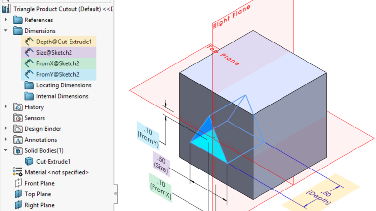
- Add smart dimensions to the library feature sketch, creating relations between sketch geometry and planes. In the screenshot below, FromX is dimensioned to the Right Plane, and FromY is dimensioned to the Top Plane.
- Rename dimensions for easy identification and use downstream in DriveWorks.
- Make sure the dimensions appear in the Dimensions folder within the FeatureManager Tree in the library feature.

Library feature sketch dimensions and FeatureManagerTree
In DriveWorks Administrator, you’ll reference these named dimensions in the Size Dimension Names list (they must appear in the same order as in SOLIDWORKS). Then, in the Size Dimension Values list, provide corresponding values; these can be fixed, calculated from rules, or driven by form inputs.

Insert Library Feature Generation Task with corresponding values from Library Feature
2. Preparing Parts in SOLIDWORKS
Before DriveWorks can insert a library feature, the part must have clearly defined reference geometry, like naming the face where the feature should go. Think of it like preparing a jig in a factory. Without clear instructions, automation won’t know where to go or what to do.
Key Preparation Steps:
- Name the Face – Right-click the target face, go to Face Properties, and then assign a name.
- Create Matching Planes – If your library feature references planes like XPlane and YPlane, create these planes in the part and use the exact names. This ensures DriveWorks can match them during insertion.
In the example above, DriveWorks is set up to look for two planes named XPlane and YPlane to position the library feature. These planes need to exist in the SOLIDWORKS part file. During automation, DriveWorks locates these planes and inserts the library feature based on their position. This setup gives DriveWorks everything it needs to insert features predictably and consistently.
3. Generation Task in DriveWorks Administrator
Finally, you’ll set up the Insert Library Feature Generation Task in DriveWorks Administrator.
The key fields for DriveWorks automation are:
- Filename – Provide the full path to the .SLDLFP file. Remember to include the extension in the file path.
- Configuration Name – If your library feature uses configurations, build a rule to select the appropriate one.
For example: “Style” & LockStyleReturn → could evaluate to Style1, Style2, or Style3 depending on the form input called LockStyle. Dynamic rule for Configuration Name
 - Face Name – Matches the name assigned in SOLIDWORKS to the face receiving the feature.
- Plane Names – Enter the case-sensitive names of the reference planes your library feature needs. For this Generation Task, the order of the Planes is important too. If the order doesn’t match the order in which the Planes are captured in the References folder, the task will not work.

Order of planes in the References folder
By combining the power of SOLIDWORKS Library Features with DriveWorks automation, you can scale your design processes efficiently. Whether you’re automating simple holes or complex cutouts with parametric control, this workflow saves time, boosts accuracy, and makes your design automation more flexible.
To learn more about using DriveWorks for SOLIDWORKS automation, contact us here.
Cloud Software
Berita Olahraga
Lowongan Kerja
Berita Terkini
Berita Terbaru
Berita Teknologi
Seputar Teknologi
Berita Politik
Resep Masakan
Pendidikan