Creating complex and smooth transitions between different shapes is a crucial skill in 3D modeling, and SOLIDWORKS offers a powerful tool to achieve this: the Loft feature. Whether you’re designing sleek automotive parts, intricate consumer products, or innovative architectural elements, understanding how to effectively use lofts can elevate your designs to a new level. In this tech tip and blog, we’ll dive into the fundamentals of lofting in SOLIDWORKS, explore practical applications, and provide step-by-step instructions to help you master this essential technique.
What is a Loft in SOLIDWORKS?
The Loft feature in SOLIDWORKS is a tool that allows you to create a smooth, flowing shape by connecting multiple profiles (cross-sections) along a path or by using a guide curve to connect the start and end faces of a part. Think of it like stretching a piece of fabric over a series of hoops of different sizes and shapes; the fabric forms a smooth surface that connects all the hoops seamlessly. This is essentially what a loft does in SOLIDWORKS, but with 3D geometry.
Creating a Loft
There are two main ways to create lofted features in SOLIDWORKS, and you can use them interchangeably depending on what you’re creating. Today I’ll be making a cool vase for my desk, so I’ll make two different versions. For the first, we’ll use a few guide curves along with my top and bottom profiles, and for the second, I’ll use multiple profiles with no guide curves.
Method 1 – Using Guide Curves
Step 1: Creating our Start/End Faces
For our vase, we’ll add two simple start and end profiles to act as the top and bottom for our loft feature to connect. We’ll sketch an ellipse on our Top Plane, align it to the origin, and add relations and dimensions to fully define it.
 Bottom profile sketched onto the Top Plane
To sketch my top opening for my vase, I need to create a reference plane normal to the Top Plane. Once I have my new plane, I’ll sketch a circle and fully define it as well.

Both sketch profiles needed for a SOLIDWORKS Loft
Step 2: Creating a Guide Curve
Since this is the “guide curve” method of creating my loft, I’ll sketch some splines on my Front and Right planes to help define the overall shape of my vase. The number one thing I’m making sure of is that there are coincident relationships to the profiles from either end of the splines, since I want everything connected. You can experiment with creating as many guide curves as you want to define your finished shape. In my example below, I create four guide curves to define the shape on either side. Combining some additional sketching techniques like converting entities and mirroring them over existing planes, I’m left with a skeleton or wireframe of my vase.

Guide curves intersecting my top and bottom profiles
Step 3: Using the Lofted Boss/Base Feature
We’ve got our framework for our vase, so we can now create our loft feature. Exit the sketch and select the “Lofted Boss/Base” feature. Select the top and bottom sketch profiles for the Profiles group box. You can select them in whichever order you want and use the arrows to reorder afterwards. This is to signify the start and end profiles to which you can then add start and end constraints. In the Guide Curves group box, select all the guide curves you have created, and you’ll see our vase start to take shape.

Preview of a Lofted Boss/Base feature in SOLIDWORKS
Method 2 – Using Multiple Profiles
Step 1: Creating our Reference Geometry
Let’s try things a different way to see how we can create a loft feature using only profiles. The first step will be creating my additional planes where I can sketch my profiles. I’ll create three additional planes, all offset by 30mm from the last. I like to think of these like unique cross-sections of my final part.
We’ll create a profile sketch on each of these planes, ensuring they’re fully defined each time. Just like we did previously, you can create as many profiles as you want to help control the curvature of the final part.

Completed sketches to use as the loft profiles
Step 2: Using the Lofted Boss/Base Feature
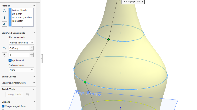
Since we have created our profiles for the cross-sections of our vase, we can exit out of our sketches and select the Lofted Boss/Base command to open the PropertyManager. Starting either from the bottom sketch up to the top or vice versa, you can select your profiles. As you do this, you’ll see the preview of your part take shape. Once you have all of them, you can play with the Start/End Constraints section to see how changes affect your part. For my vase, I’ll set the start constraint to “Normal to Profile”, which means SOLIDWORKS will add a tangency to the starting profile, or in this case, my bottom sketch.

Lofted SOLIDWORKS part using multiple profiles
For morning information about the constraint options in the Loft Property Manager, check out Loft with Start and End Constraints – 2025 – SOLIDWORKS Help
Finishing the Vases
Whichever way you prefer to create your lofted feature, you’ll be left with a nice piece of geometry that follows a more organic, elegant shape. Since I was making a vase, I’ll put some finishing touches on both designs. I’ll shell out both and choose a color that fits me…and voila!

Completed vase using the multiple profiles method
From sleek automotive curves to ergonomic consumer products, lofts are your ticket to creating stunning, complex designs with ease. So, next time you’re faced with a challenging project, remember that the loft tool is your trusty sidekick, ready to transform your ideas into reality. Happy lofting, and may your designs always be smooth and spectacular!
To have more time-saving SOLIDWORKS Tips and Tricks delivered right to your inbox, subscribe to our bi-weekly newsletter here!
Cloud Software
Motivation
News
Berita Olahraga
Berita Olahraga
Anime Batch
News
Pelajaran Sekolah
Berita Terkini
Berita Terkini