When sketching in SOLIDWORKS, angled lines can sometimes pose a challenge when it comes to defining their angle relative to some “global” horizontal or vertical reference. In cases where there is no existing reference geometry to dimension an angled line to, keep in mind that you can dimension an angled line to itself!
A common practice is to sketch a reference or construction line in one of those directions, and then use the Smart Dimension tool between the construction line and the angled sketch line. While it’s not wrong to use this method, there is a lesser-known shortcut that can speed up your design process and eliminate unnecessary sketch clutter. We’ll discuss both methods below!
Sketching Extra Construction Geometry
One method for dimensioning hard-to-define angled lines is to sketch a construction line with a horizontal or vertical relation on it. This new dashed line can serve as a generic horizontal or vertical reference when using the Smart Dimension tool to apply an angle dimension. In the image below, I’ve created two sketches with two different ways of using a construction line as a reference for creating an angle to the horizontal.
 Dimensioning with a horizontal construction line
These construction lines can definitely be useful if you want to visualize a centerline or how multiple dimensions relate to the same “global” horizontal reference. However, I have seen many cases where a sketch has one construction line for each angled line, leading to a cluttered sketch with too much construction geometry. In cases like this, I would recommend the following pro-tip.
Dimension an Angled Line to an Implied Horizontal or Vertical
In cases where there is no existing reference geometry to dimension an angled line to, keep in mind that you can dimension an angled line to itself!
Here are the steps:
- Activate the Smart Dimension tool.
- Click the angled line.
- Click an endpoint of the line (select the endpoint that you want to be “touching” the global horizontal or vertical).
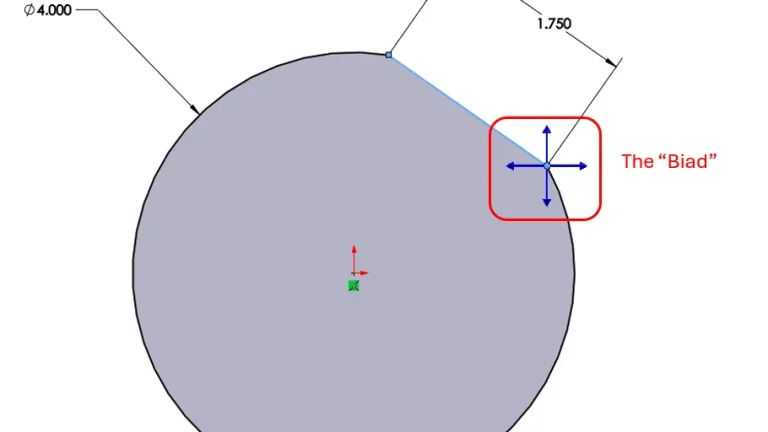
- The “Biad” appears. Click one of the vertical or horizontal arrows.
 Using the SOLIDWORKS Biad
 - Move the dimension (moving the dimension above or below the horizon line will produce different results) and click to place it.
- Use the Modify box to enter the angle value.
 Creating the angle without unnecessary geometry
While creating a construction line to represent the sketch’s horizontal or vertical reference isn’t wrong, it is a process that can easily be overused, leading to cluttered sketches with multiple reference lines getting in the way of your design. In cases where an angle dimension can be connected to an implied horizontal or vertical reference, the Biad is a very effective tool to use.
Want more tips like these delivered directly to your inbox? Sign up for our Tech Tip Newsletter here.
Cloud Software
Berita Olahraga
Lowongan Kerja
Berita Terkini
Berita Terbaru
Berita Teknologi
Seputar Teknologi
Berita Politik
Resep Masakan
Pendidikan