When doing assembly modeling in SOLIDWORKS, we usually use the Move Component command by left or right-clicking a component and then dragging the cursor. This interactive approach is great for most operations, but it can be challenging to move components precisely.
Drag moves are always in plane with your view orientation, and the final location isn’t always predictable or obvious. Luckily, when we explicitly issue the Move Component command, we are presented with a suite of options that allow us to move components with confidence and control.
With the Move Component command, you can:
- Move components while honoring assembly mates and degrees of freedom
- Use live collision detection during movement
- Check clearances between components during movement
- Run dynamic physics studies to move components without mates
Movement Options in the Move Component Command
Through the standard options of the Move Component command, you have access to a few different translation and rotation methods. Each has its own use case and can be used to locate a component in space.
Move Along Assembly XYZ
One way to constrain click-drag movement is to select Along Assembly XYZ in the Property Manager. A triad appears on the origin, and you click on one of the triad’s axes to specify the move direction.
 Moving assembly components along cardinal planes
Now, cursor moves allow dragging motion only in the selected direction, regardless of the view orientation. To change the move direction, click on one of the triad’s other axes and resume your click-drag.
Movement Along an Entity
We can also constrain component movement along a specific edge or face. Selecting a line, linear edge, or axis allows drag only in the direction of that vector.

Dragging a component along an edge
If a plane or planar face is selected, then the component can be dragged anywhere in-plane with two degrees of freedom. A comparable Rotate option, About Entity, lets you select a line, linear edge, or axis as the axis reference.
Move (or Rotate) By Delta XYZ
Sometimes we want to precisely move or rotate a component relative to its current position. A simple drag motion is inadequate for this, and assembly mates can get you there, but they remove components’ degrees of freedom.

Moving components by a delta value
The By Delta XYZ option is perfect for these situations where accuracy is required. Just enter the relative X, Y, and Z values, and each time the apply button is pressed, the component(s) move the specified distance. The rotate option rotates components by the specified angle about the assembly’s XYZ axes.
Move to XYZ Position
This option is useful when you know the exact location where a component should be placed. Type in the absolute X, Y, and Z location values with respect to the default coordinate system to move the component so that the origin of the component is coincident with the specified location.

Locating a part to a specific coordinate position
Again, these explicit techniques allow us to transform components with much more accuracy and precision than simple dragging.
Collision Detection
The Interference Detection command can show where components in an assembly overlap, but it only works for the current positioning. It cannot tell us if an interference will occur at any other positions as the mechanism moves through its range of motion.
Fortunately, Collision Detection in the Move Component command lets us evaluate a mechanism’s component interactions across its range of motion. After activating the Collision Detection option, specifying the components to consider, and setting the feedback options, you then drag the mechanism through its range of motion.
When two components collide with each other, the mechanism stops as it would in the real world, and the colliding faces get highlighted. If the mechanism is starting in an interfering state, a warning will appear. You can still drag through the motion, but it will not stop at a collision.
Dynamic Clearance
Having adequate clearance between assembly components is just as important as ensuring no interference. SOLIDWORKS assemblies are mathematically and topologically accurate, but real-world manufacturing and assembly are considerably less precise. We must account for this, and understanding clearances between components in a perfect assembly can guide our designs, inform acceptable tolerances, and suggest manufacturing choices.
The Dynamic Clearance option allows you to select two components in the assembly and drag the mechanism through its range of motion. A dimension appears in the graphics area at the location where the two parts are closest to each other, and the dynamic dimension reporting updates as the mechanism is cycled.

Clearance calculations in the Move Component command
As components are dragged, the Property Manager displays the current smallest clearance and the absolute minimum gap across the entire range of motion.
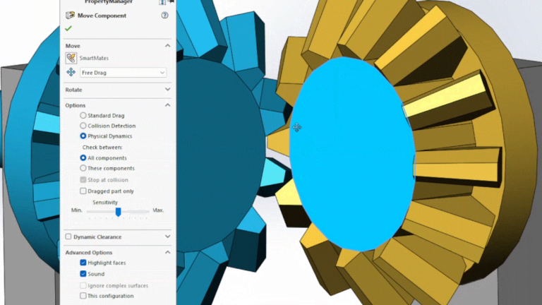
Physical Dynamics
As mentioned earlier, SOLIDWORKS models are mathematically and topologically accurate, and this also applies to assembly mates. Simple drag action allows components to collide and interfere with no restrictions while they move through their range of motion.
Physical Dynamics is a rudimentary but valuable motion analysis tool that allows us to see the motion of an assembly in a realistic way. Components are not allowed to interfere, and when one component collides with another component, it applies a force. The other component then moves through its range of motion.

Showing imperfect motion with Physical Dynamics
To use Physical Dynamics, activate the option and select the components to be considered, and then click-drag one of the components through its range of motion. In the image above, a gear mate would impose perfect 1:1 motion, and the teeth might never touch, so Physical Dynamics is used to better understand the true mechanism action and backlash encountered.
To learn additional lesser-known SOLIDWORKS workflows, sign up for our bi-weekly Tech Tip Newsletter here.
PakarPBN
A Private Blog Network (PBN) is a collection of websites that are controlled by a single individual or organization and used primarily to build backlinks to a “money site” in order to influence its ranking in search engines such as Google. The core idea behind a PBN is based on the importance of backlinks in Google’s ranking algorithm. Since Google views backlinks as signals of authority and trust, some website owners attempt to artificially create these signals through a controlled network of sites.
In a typical PBN setup, the owner acquires expired or aged domains that already have existing authority, backlinks, and history. These domains are rebuilt with new content and hosted separately, often using different IP addresses, hosting providers, themes, and ownership details to make them appear unrelated. Within the content published on these sites, links are strategically placed that point to the main website the owner wants to rank higher. By doing this, the owner attempts to pass link equity (also known as “link juice”) from the PBN sites to the target website.
The purpose of a PBN is to give the impression that the target website is naturally earning links from multiple independent sources. If done effectively, this can temporarily improve keyword rankings, increase organic visibility, and drive more traffic from search results.